Entity-Relationship Diagrams (ERDs)
Entity-Relationship Diagrams (ERDs) are a fundamental tool in database and software design, providing a graphical representation of the entities, their attributes, and the relationships between them within a system.
This article delves into the world of ER Diagrams, covering their introduction, components, and practical examples to offer a comprehensive understanding of their application and significance in modeling real-world systems.
Introduction to ER Diagrams
ER Diagrams stand as a pivotal method for conceptualizing and visualizing the data relationships and structure of database systems.
Originating from the ER Model proposed by Peter Chen in 1971, ER Diagrams have evolved to become an essential part of database design and analysis.
They serve not only as a blueprint for constructing relational databases but also as a communication tool among stakeholders to understand system requirements clearly.
The strength of ER Diagrams lies in their ability to represent complex data structures in an intuitive and accessible manner.
By drafting entities (such as people, places, objects, or concepts) and the relationships among them, ER Diagrams facilitate a deeper understanding of how data interacts within a system, which is crucial for both database design and business process modeling.
Components of ER Diagrams
ER Diagrams consist of several key components that represent the various aspects of a database system:
- Entities: These are the primary components of an ER Diagram, representing objects or concepts that hold data within the system. Entities are depicted as rectangles and are typically nouns, such as 'Book', 'Author', or 'Publisher'.
- Attributes: Attributes provide details about the entities, describing their properties or characteristics. Represented by ovals connected to their respective entities, attributes can be simple (single-valued), composite (having multiple components), derived (calculated from other attributes), or multi-valued (having more than one value).
- Relationships: Relationships illustrate how entities are related to each other within the system. They are depicted by diamonds and can be one-to-one, one-to-many, or many-to-many, providing a clear picture of the interactions between entities.
- Cardinality and Modality: These notations specify the nature and degree of relationships between entities, indicating how many instances of an entity relate to instances of another entity. Cardinality defines the numerical aspects of a relationship, while modality indicates the necessity of the relationship.
Practical Examples of ER Diagrams
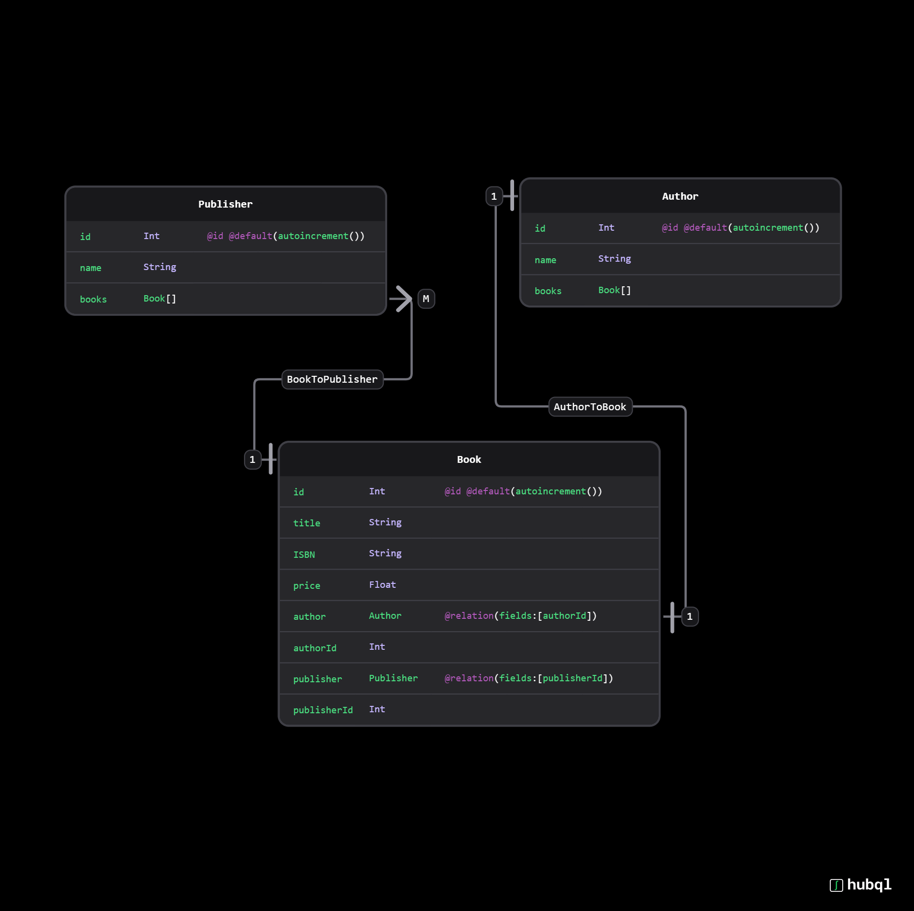
To illustrate the application of ER Diagrams, consider a simple database system for a bookstore:
- Entities: 'Book', 'Author', and 'Publisher'.
- Attributes: For 'Book' - Title, ISBN, and Price. For 'Author' - Name and Bio. For 'Publisher' - Name and Address.
- Relationships: 'Written by' between 'Book' and 'Author' indicating which author wrote which book, and 'Published by' between 'Book' and 'Publisher' showing which publisher published which book. This example demonstrates how ER Diagrams can effectively model the relationships between different entities within a system, providing a clear and organized overview of the data structure.

Conclusion
ER Diagrams are a vital tool in the realm of database design and system analysis, offering a clear and structured way to visualize the relationships and attributes of entities within a system.
By understanding the components and practical applications of ER Diagrams, designers and analysts can effectively model and communicate complex data structures, facilitating the development of efficient and robust database systems.
With Hubql, you can generate ER-Diagrams automatically from your code defined in Prisma or SQL. You can collaborate with your team and discuss data schemas together.
Ready to turbo-charge your next software development project?
Get started today for free and stay up to date with your upcoming new features and integrations with your favorite services.